Three phase auto changer circuit
This circuit is a modification of High & Low voltage cut-off with delay& alarm circuit appeared in Circuits today, which I have tried and found to be quite reliable. You can adopt this circuit with small modification. Use a transformer with secondary 15 – 0 – 15 AC Volt at 500mA, for 18Volt relay operation. Normally any modern electrical / electronic equipment can operate with 230 Volt ± 15% AC supply. That is, it can stand normal voltage operating range of 195 to 265 Volts. It may misbehave beyond this voltage range. You can choose the practical voltage required for the low end high cut off to change over to other phase.
Circuit diagram.
Connection diagram.

Notes.
- Set VR3 for minimum voltage to switch on the relay (Say 195 Volt input).
- Set VR1 to switch off the relay above a particular voltage (say 260Volt input).
- You can use a 100μF 40 Volts good make in parallel with relay for chatter free operation.
- Each Phase you have to use one module as above.
- The relay interconnections are shown in the connection diagram above.
- T1 can be a 15-015 V secondary, 230V primary, 500mA step down transformer.
Read more: http://www.circuitstoday.com/##ixzz0kOSJKacN
Under Creative Commons License: Attribution
100 Watt inverter circuit
Description
Here is a 100 Watt inverter circuit using minimum number of components.I think it is quite difficult to make a decent one like this with further less components.Here we use CD 4047 IC from Texas Instruments for generating the 100 Hz pulses and four 2N3055 transistors for driving the load.
The IC1 Cd4047 wired as an astable multivibrator produces two 180 degree out of phase 100 Hz pulse trains.These pulse trains are preamplifed by the two TIP122 transistors.The out puts of the TIP 122 transistors are amplified by four 2N 3055 transistors (two transistors for each half cycle) to drive the inverter transformer.The 220V AC will be available at the secondary of the transformer.Nothing complex just the elementary inverter principle and the circuit works great for small loads like a few bulbs or fans.If you need just a low cost inverter in the region of 100 W,then this is the best.
Circuit Diagram with Parts List.

Notes.
- A 12 V car battery can be used as the 12V source.
- Use the POT R1 to set the output frequency to50Hz.
- For the transformer get a 9-0-9 V , 10A step down transformer.But here the 9-0-9 V winding will be the primary and 220V winding will be the secondary.
- If you could not get a 10A rated transformer , don’t worry a 5A one will be just enough. But the allowed out put power will be reduced to 60W.
- Use a 10 A fuse in series with the battery as shown in circuit.
- Mount the IC on an IC holder.
- Remember,this circuit is nothing when compared to advanced PWM inverters.This is a low cost circuit meant for low scale applications.
Design Tips.
The maximum allowed output power of an inverter depends on two factors.The maximum current rating of the transformer primary and the current rating of the driving transistors.
For example ,to get a 100 Watt output using 12 V car battery the primary current will be ~8A ,(100/12) because P=VxI.So the primary of transformer must be rated above 8A.
Also here ,each final driver transistors must be rated above 4A. Here two will be conducting parallel in each half cycle, so I=8/2 = 4A .
These are only rough calculations and enough for this circuit.
Musical horn circuit.
Description.
Here is a simple circuit diagram of a simple musical horn using two NE555 ICs.Two ICs are wired as astable mutivibrators.The ouput of first multivibrator is given to the discharge (pin 7) of the second astable multivibrator.The combined effect of the astable multivibrators produce a musical tone at the output.
Circuit diagram with Parts list.
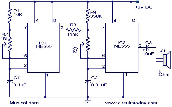
Notes.
- The sound effect can be adjusted by varying the POTs R2&R5.
- The speaker can be a 8 Ohm tweeter.
- The circuit can be powered from a 9V PP3 battery.
- The ICs must be mounted on holders.
- All capacitors must be rated 15V.