100 Watt sub woofer amplifier.
Description.
This is the circuit diagram of a fully transistorized sub woofer amplifier that can produce an output of 100W.There are seven transistors including four in the output stage. The transistors Q1 and Q2 form the preamplifier stage. Transistors Q4 to Q7 form the output stage. Since no ICs are used the circuit is very robust and can be easily assembled on a general purpose PCB.
This is the circuit diagram of a fully transistorized sub woofer amplifier that can produce an output of 100W.There are seven transistors including four in the output stage. The transistors Q1 and Q2 form the preamplifier stage. Transistors Q4 to Q7 form the output stage. Since no ICs are used the circuit is very robust and can be easily assembled on a general purpose PCB.
Circuit diagram with Parts list.

Notes.
- The circuit can be powered from a +35V/-35V, 5A dual power supply.
- Use a 100W, 12 inch sub woofer at the output.
- All electrolytic capacitors must be rated 100V.
- The transistor Q4 to Q7 must be fitted with heat sinks.
Read more: http://www.circuitstoday.com/100-watt-sub-woofer-amplifier#ixzz0kx4XC5B5
Under Creative Commons License: Attribution
150 Watt amplifier circuit
Description
This is the cheapest 150 Watt amplifier circuit you can get,I think.Based on two Darlington power transistors TIP 142 and TIP 147 ,this circuit can deliver a blasting 150 W Rms to a 4 Ohm speaker.Enough for you to get rocked?,then try out this.

Notes.
This is the cheapest 150 Watt amplifier circuit you can get,I think.Based on two Darlington power transistors TIP 142 and TIP 147 ,this circuit can deliver a blasting 150 W Rms to a 4 Ohm speaker.Enough for you to get rocked?,then try out this.
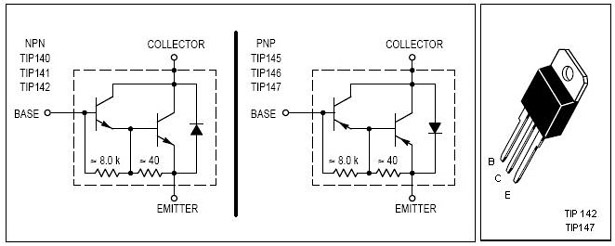
TIP 147 and 142 are complementary Darlington pair transistors which can handle 5 A current and 100V ,famous for their ruggedness. Here two BC 558 transistorsQ5 and Q6 are wired as pre amplifier and TIP 142 ,TIP 147 together with TIP42 (Q1,Q2,Q3) for driving the transistors.This circuit is designed so rugged that this can be assembled even on a common board or even by pin to pin soldering.The circuit can be powered from a +/-45V 5A dual power supply.You must try this circuit.Its working great.
Circuit Diagram & Parts List .Notes.
- Remember TIP 142 and 147 are Darlington pairs .They are shown as conventional transistors in figure for ease.So don’t get confused.Even though each of them have 2 transistors ,2 resistors and 1 diode inside ,only three pins ,base emitter and collector are coming out.Rest are connected internally.So its quite OK to assume each of them as transistor for ease.
- Use a well regulated and filtered power supply.
- Connect a 10K POT in series with the input as volume control if you need.Not shown in circuit diagram.
100 Watt inverter circuit
Description
Here is a 100 Watt inverter circuit using minimum number of components.I think it is quite difficult to make a decent one like this with further less components.Here we use CD 4047 IC from Texas Instruments for generating the 100 Hz pulses and four 2N3055 transistors for driving the load.
The IC1 Cd4047 wired as an astable multivibrator produces two 180 degree out of phase 100 Hz pulse trains.These pulse trains are preamplifed by the two TIP122 transistors.The out puts of the TIP 122 transistors are amplified by four 2N 3055 transistors (two transistors for each half cycle) to drive the inverter transformer.The 220V AC will be available at the secondary of the transformer.Nothing complex just the elementary inverter principle and the circuit works great for small loads like a few bulbs or fans.If you need just a low cost inverter in the region of 100 W,then this is the best.
Circuit Diagram with Parts List.

Notes.
- A 12 V car battery can be used as the 12V source.
- Use the POT R1 to set the output frequency to50Hz.
- For the transformer get a 9-0-9 V , 10A step down transformer.But here the 9-0-9 V winding will be the primary and 220V winding will be the secondary.
- If you could not get a 10A rated transformer , don’t worry a 5A one will be just enough. But the allowed out put power will be reduced to 60W.
- Use a 10 A fuse in series with the battery as shown in circuit.
- Mount the IC on an IC holder.
- Remember,this circuit is nothing when compared to advanced PWM inverters.This is a low cost circuit meant for low scale applications.
Design Tips.
The maximum allowed output power of an inverter depends on two factors.The maximum current rating of the transformer primary and the current rating of the driving transistors.
For example ,to get a 100 Watt output using 12 V car battery the primary current will be ~8A ,(100/12) because P=VxI.So the primary of transformer must be rated above 8A.
Also here ,each final driver transistors must be rated above 4A. Here two will be conducting parallel in each half cycle, so I=8/2 = 4A .
These are only rough calculations and enough for this circuit.