High & Low voltage cut-off with delay& alarm
Description.
This straight forward circuit will protect electrical appliances from over voltage as well as under voltage.The circuit also produces an alarm when the power supply comes back.An ideal circuit for home to protect your valuable equipments from voltage fluctuations.The same circuit with some modifications can be used to make a automatic voltage stabilizer.
When the mains voltage is in the normal level ,the voltage at the negative terminal of zener diode D4 will be less than 5.6 Volts.At this condition transistor T1 will not conduct.The same time voltage at the negative terminal of zener diode D5 will be greater than 5.6 and so the transistor T2 will be conducting.The relay will be activated and the green LED wil be glowing.
When the mains voltage is higher than the set limit the transistor T1 becomes conducting since the voltage at the negative terminal of D4 is greater than 5.6 V.At the same time transistor T2 will be non conducting which results in the deactivation of relay to cut the mains supply from load.When the mains voltage is less than the set limit transistors T1 & T2 becomes non conducting making the relay to de- activate and cut the load from mains.Ω
The timer NE555 is wired as a monostable multivibrator with a pulse width of 10ms.When the power comes back after a cut off a negative voltage is obtained at the trigger pin which triggers the IC NE555.The transistor T3 gets forward biased and it drives the buzzer to produce a beep as an indication of power resumption.Also the transistor T1 is made on which in turn makes T2 off.As a result the relay will remain de- activate for 10ms and this provides the sufficient delay and the equipment is protected from surge voltages.
Circuit diagram with Parts list.Click to enlarge.

Notes.
- To calibrate the circuit a autotransformer is needed.Connect the output of autotransformer to the transformer primary.
- Set the voltage to 260V and adjust VR1 to make the relay deactivated.
- Now set the autotransformer to 160V and adjust VR2 so that the relay is de-energized.
- VR3 can be used to vary the volume of buzzer.
Parking sensor circuit
Description.
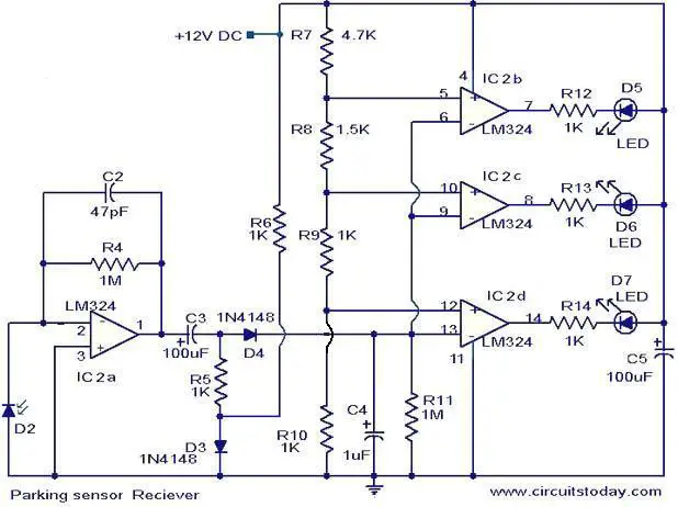
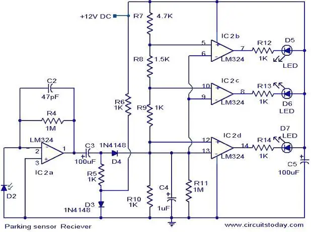
This simple circuit can be used as an aid for sensing the distance between the rear bumper of the car and any obstacle behind the car. The distance can be understood from the combination of the LEDs (D5 to D7) glowing. At 25cm D7 will glow, at 20 cm D7&D6 will glow and at 5cm D7, D6 and D5 will glow. When the obstacle is beyond 25 cm none of the above LEDs will glow.
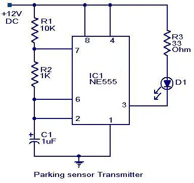
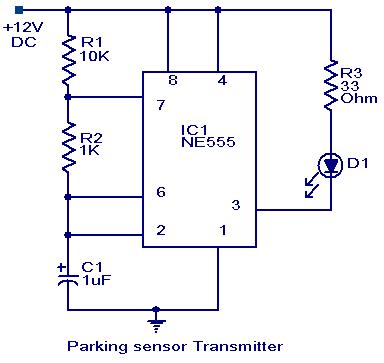
Two ICs are used in the circuit. The IC1 (NE555) is wired as an astable multivibrator for driving the IR Diode D1 to emit IR pulses. The operating frequency of the transmitter is set to be 120Hz.The IR pulses transmitted by D1 will be reflected by the obstacle and received by the D2 (IR photo diode).The received signal will be amplified by IC2a.The peak of the amplified signal will be detected by the diode D4 and capacitor C4.R5 and R6 compensates the forward voltage drop of D4.The output voltage of the peak detector will be proportional to the distance between car’s bumper and obstacle. The output of peak detector is given to the inputs of the other three comparators IC2b,IC2c and IC2d inside the IC2(LM324).The comparators switch the status LEDs according to the input voltage their inverting inputs and reference voltages at their non inverting inputs. Resistances R7 to R10 are used to set the reference voltages for the comparators.
Circuit diagram with Parts list.
Notes.
- Assemble the circuit on a good quality PCB or common board.
- The D1 & D2 must be mounted close (~2cm) to each other, looking in same direction.
- The D1 can be a general purpose IR LED.
- The D2 can be general purpose IR photo diode with sun filter.
- The transmitter as well as receiver can be powered from the car battery.
- For proper working of the circuit, some trial and error is needed with the position of D1 and D2 on the dash board.
- All capacitors must be rated 25V.
- The ICs must be mounted on holders.
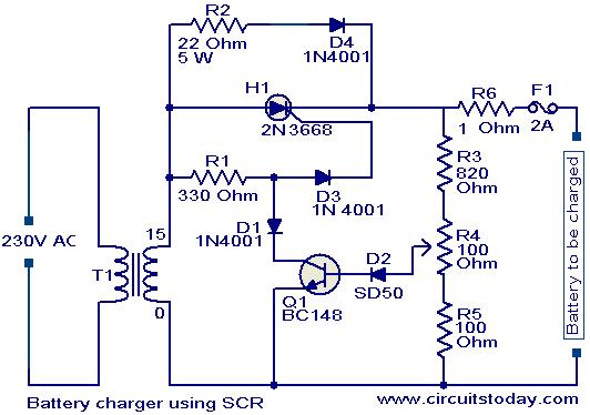
Battery charger circuit using SCR.
Description.
A simple battery charger based on SCR is shown here.Here the SCR rectifies the AC mains voltage to charge the battery.When the battery connected to the charger gets discharged the battery voltage gets dropped.This inhibits the forward biasing voltage from reaching the base of the transistor Q1 through R4 and D2.This switches off the transistor.When the transistor is turned OFF,the gate of SCR (H1) gets the triggering voltage via R1 & D3.This makes the SCR to conduct and it starts to rectify the AC input voltage.The rectified voltage is given to the battery through the resistor R6(5W).This starts charging of the battery.
When the battery is completely charged the base of Q1 gets the forward bias signal through the voltage divider circuit made of R3,R4,R5 and D2.This turns the transistor ON.When the Q1 is turned ON the trigger voltage at the gate of SCR is cut off and the SCR is turned OFF.In this condition a very small amount of charge reaches the battery via R2 and D4 for trickle charging.Since the charging voltage is only half wave rectified ,this type of charger is suitable only for slow charging.For fast charging full wave rectified charging voltage is needed.
When the battery is completely charged the base of Q1 gets the forward bias signal through the voltage divider circuit made of R3,R4,R5 and D2.This turns the transistor ON.When the Q1 is turned ON the trigger voltage at the gate of SCR is cut off and the SCR is turned OFF.In this condition a very small amount of charge reaches the battery via R2 and D4 for trickle charging.Since the charging voltage is only half wave rectified ,this type of charger is suitable only for slow charging.For fast charging full wave rectified charging voltage is needed.
Circuit diagram with Parts list.
Notes.
- Assemble the circuit on a good quality PCB or common board.
- The transformer T1 can be 230V primary, 18V /3A secondary step down transformer.
- The voltage of the battery at which the charging should stop can be set by the POT R4.
- The battery can be connected to the charger circuit by using crocodile clips.
FM Radio jammer
Description.
Circuit shown here can be used to jam FM radios in its vicinity. The circuit is nothing but a classic single transistor oscillator operating in the VHF region. Working principle of the circuit is very simple and straight forward. Powerful VHF oscillations from the circuit will interfere with the FM signals to nullify it. Jammer circuits like this are illegal in many countries and you must assemble this circuit on your own responsibility. This circuit is intended only for fun and i request you not to misuse it.
Circuit diagram.

Notes.
- For L1 make 6 turns of 16AWG enamelled copper wire on a 9mm plastic former.
- The circuit can be powered using a 9V PP3 battery.
- For extended range, use an antenna.
- A 30cm long wire connected anywhere on the coil will do for the antenna.
- For better performance, assemble the circuit on a good PCB.